Benutzer:RRST93/Marine steam engine

Eine Schiffsdampfmaschine ist eine Dampfmaschine, die zum Antrieb eines Schiffes oder Bootes dient. Dieser Artikel befasst sich mit Kolbendampfmaschinen, welche von den Anfängen des Dampfschiffs zu Beginn 19. Jahrhundert bis in die Zeit nach dem Zweiten Weltkrieg im Einsatz waren. Schiffsdampfmaschinen wurden ab dem ersten Jahrzehnt des 20. Jahrhundert zunehmend durch Dampfturbinen und Schiffsdieselmotoren ersetzt.
Geschichte[Bearbeiten | Quelltext bearbeiten]
Die Dampfmaschine wurde von Thomas Newcomen im Jahr 1712 erfunden und in der zweiten Hälfte des 18. Jahrhunderts von James Watt zur Reife gebracht. Zu Beginn des 19. Jahrhundert gelang es William Symington die Dampfmaschine auch für den Schiffsbetrieb zu adaptieren, mit der Charlotte Dundas konstruierte er 1802 das erste praktisch verwendbare Dampfschiff.[1] 1807 baute der Amerikaner Robert Fulton das erste kommerziell erfolgreiche Dampfschiff North River Steamboat, angetrieben von einer Watt´schen Dampfmaschine.
Nach dem Erfolg von Fultons Schiff entwickelte sich die Dampfschiff-Technik auf beiden Seiten des Atlantiks rasch weiter. Steamboats initially had a short range and were not particularly seaworthy due to their weight, low power, and tendency to break down, but they were employed successfully along rivers and canals, and for short journeys along the coast. The first successful transatlantic crossing by a steamship occurred in 1819 when Savanna ailed from Savannah, Georgia to Liverpool. The first steamship to make regular transatlantic crossings was the sidewheel steamer Vorlage:SS in 1838.[2]
As the 19th century progressed, marine steam engines and steamship technology developed alongside each other. Paddle propulsion gradually gave way to the screw propeller, and the introduction of iron and later steel hulls to replace the traditional wooden hull allowed ships to grow ever larger, necessitating steam power plants that were increasingly complex and powerful.[3]
Typen von Schiffsdampfmaschinen[Bearbeiten | Quelltext bearbeiten]

Im Laufe des 19. Jahrhunderts wurde eine Vielzahl von kolbengetriebenen Schiffsdampfmaschinen entwickelt. Die beiden Hauptmethoden zur Klassifizierung solcher Maschinen sind die Art des Antriebes und die Bauart der Zylinder.
Die meisten frühen Schiffsdampfmaschinen hatten die gleiche Zylinderbauart, es wurden jedoch eine Reihe verschiedener Methoden zur Kraftübertragung an die Kurbelwelle (sprich der Verbindungsmechanismus) verwendet. Daher werden frühe Schiffsmotoren hauptsächlich nach ihrem Verbindungsmechanismus klassifiziert. Einige gebräuchliche Verbindungsmechanismen waren Balancier, Seitenhebel, oszillierend bzw. schrägliegend (siehe folgende Abschnitte).
Dampfmaschinen können aber auch nach der Bauart der Zylinder (einfache Expansion, Verbundmaschine, Gleichstrommaschine etc.) eingeteilt werden. Viele Typen von Schiffsdampfmaschinen können daher mit beiden Methoden klassifiziert werden. Eine Maschine kann eine oszillierende Verbunddampfmaschine sein, wobei oszillierend die Verbindungsmethode ist und Verbund die Bauart der Zylinder. Im Laufe der Zeit, als die meisten Maschinen direktwirkend geworden waren und die Bauart der Zylinder zunehmend komplexer wurde, begann man, die Maschinen ausschließlich nach den Zylindern zu klassifizieren.
In Europa häufiger anzutreffende Schiffsdampfmaschinentypen sind in den folgenden Abschnitten aufgeführt. Beachten Sie, dass nicht alle diese Begriffe ausschließlich für Schiffsanwendungen gelten und manche in Europa ungebräuchliche Bauarten in der englischen Version des Artikels zu finden sind.
Definition über die Art des Antriebes[Bearbeiten | Quelltext bearbeiten]
Indirekter Antrieb über Hebel[Bearbeiten | Quelltext bearbeiten]
Seitenhebel-Balanciermaschine (side-lever engine)[Bearbeiten | Quelltext bearbeiten]
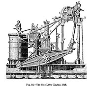
Die Seitenhebel-Balanciermaschine war in der ersten Hälfte des 19. Jahrhunderts die meist genutzte Schiffsmaschinentype in Europa.[4][5] In the early years of steam navigation (from c1815), the side-lever was the most common type of marine engine for inland waterway and coastal service in Europe, and it remained for many years the preferred engine for oceangoing service on both sides of the Atlantic.[6]
The side-lever was an adaptation of the earliest form of steam engine, the beam engine. The typical side-lever engine had a pair of heavy horizontal iron beams, known as side levers, that connected in the centre to the bottom of the engine with a pin. This connection allowed a limited arc for the levers to pivot in. These levers extended, on the cylinder side, to each side of the bottom of the vertical engine cylinder. A piston rod, connected vertically to the piston, extended out of the top of the cylinder. This rod attached to a horizontal crosshead, connected at each end to vertical rods (known as side-rods). These rods connected down to the levers on each side of the cylinder. This formed the connection of the levers to the piston on the cylinder side of the engine. The other side of the levers (the opposite end of the lever pivot to the cylinder) were connected to each other with a horizontal crosstail. This crosstail in turn connected to and operated a single connecting rod, which turned the crankshaft. The rotation of the crankshaft was driven by the levers—which, at the cylinder side, were driven by the piston's vertical oscillation.[7]
The main disadvantage of the side-lever engine was that it was large and heavy.[5] For inland waterway and coastal service, lighter and more efficient designs soon replaced it. It remained the dominant engine type for oceangoing service through much of the first half of the 19th century however, due to its relatively low centre of gravity, which gave ships more stability in heavy seas.[6] It was also a common early engine type for warships,[8] since its relatively low height made it less susceptible to battle damage. From the first Royal Navy steam vessel in 1820 until 1840, 70 steam vessels entered service, the majority with side-lever engines, using boilers set to 4psi maximum pressure.[8] The low steam pressures dictated the large cylinder sizes for the side-lever engines, though the effective pressure on the piston was the difference between the boiler pressure and the vacuum in the condenser.
The side-lever engine was a paddlewheel engine and was not suitable for driving screw propellers. The last ship built for transatlantic service that had a side-lever engine was the Cunard Line's paddle steamer Vorlage:RMS, considered an anachronism when it entered service in 1862.[9]
-
 Side-lever engine of Vorlage:SS
 -
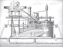 Side-lever engine of RMS Persia (1855)
 -
 Model of the twin side-lever engines of the 1836 Thames River steamboat Ruby
 -


_twin_side-lever_engine.jpg)

Grasshopper[Bearbeiten | Quelltext bearbeiten]

Vorlage:Details The grasshopper or 'half-lever'[10] engine was a variant of the side-lever engine. The grasshopper engine differs from the conventional side-lever in that the location of the lever pivot and connecting rod are more or less reversed, with the pivot located at one end of the lever instead of the centre, while the connecting rod is attached to the lever between the cylinder at one end and the pivot at the other.[11]
Chief advantages of the grasshopper engine were cheapness of construction and robustness, with the type said to require less maintenance than any other type of marine steam engine. Another advantage is that the engine could be easily started from any crank position. Like the conventional side-lever engine however, grasshopper engines were disadvantaged by their weight and size. They were mainly used in small watercraft such as riverboats and tugs.[11]
Walking beam[Bearbeiten | Quelltext bearbeiten]
The walking beam, also known as a "vertical beam", "overhead beam", or simply "beam", was another early adaptation of the beam engine, but its use was confined almost entirely to the United States.[12] After its introduction, the walking beam quickly became the most popular engine type in America for inland waterway and coastal service, and the type proved to have remarkable longevity, with walking beam engines still being occasionally manufactured as late as the 1940s. In marine applications, the beam itself was generally reinforced with iron struts that gave it a characteristic diamond shape, although the supports on which the beam rested were often built of wood. The adjective "walking" was applied because the beam, which rose high above the ship's deck, could be seen operating, and its rocking motion was (somewhat fancifully) likened to a walking motion.
Walking beam engines were a type of paddlewheel engine and were rarely used for powering propellers. They were used primarily for ships and boats working in rivers, lakes and along the coastline, but were a less popular choice for seagoing vessels because the great height of the engine made the vessel less stable in heavy seas.[13] They were also of limited use militarily, because the engine was exposed to enemy fire and could thus be easily disabled. Their popularity in the United States was due primarily to the fact that the walking beam engine was well suited for the shallow-draft boats that operated in America's shallow coastal and inland waterways.[12]
Walking beam engines remained popular with American shipping lines and excursion operations right into the early 20th century. Although the walking beam engine was technically obsolete in the later 19th century, it remained popular with excursion steamer passengers who expected to see the "walking beam" in motion. There were also technical reasons for retaining the walking beam engine in America, as it was easier to build, requiring less precision in its construction. Wood could be used for the main frame of the engine, at a much lower cost than typical practice of using iron castings for more modern engine designs. Fuel was also much cheaper in America than in Europe, so the lower efficiency of the walking beam engine was less of a consideration. The Philadelphia shipbuilder Charles H. Cramp blamed America's general lack of competitiveness with the British shipbuilding industry in the mid-to-late 19th century upon the conservatism of American domestic shipbuilders and shipping line owners, who doggedly clung to outdated technologies like the walking beam and its associated paddlewheel long after they had been abandoned in other parts of the world.[14]
-
 Basic diagram of a walking beam engine
 -
 Vorlage:USS. The vessel's diamond shaped "walking beam" can clearly be seen amidships

.jpg)
Steeple[Bearbeiten | Quelltext bearbeiten]

The steeple engine, sometimes referred to as a "crosshead" engine, was an early attempt to break away from the beam concept common to both the walking beam and side-lever types, and come up with a smaller, lighter, more efficient design. In a steeple engine, the vertical oscillation of the piston is not converted to a horizontal rocking motion as in a beam engine, but is instead used to move an assembly, composed of a crosshead and two rods, through a vertical guide at the top of the engine, which in turn rotates the crankshaft connecting rod below.[15] In early examples of the type, the crosshead assembly was rectangular in shape, but over time it was refined into an elongated triangle. The triangular assembly above the engine cylinder gives the engine its characteristic "steeple" shape, hence the name.
Steeple engines were tall like walking beam engines, but much narrower laterally, saving both space and weight. Because of their height and high centre of gravity, they were, like walking beams, considered less appropriate for oceangoing service, but they remained highly popular for several decades, especially in Europe, for inland waterway and coastal vessels.[16]
Steeple engines began to appear in steamships in the 1830s and the type was perfected in the early 1840s by the Scottish shipbuilder David Napier.[17] The steeple engine was gradually superseded by the various types of direct-acting engine.
Siamese[Bearbeiten | Quelltext bearbeiten]
The Siamese engine, also referred to as the "double cylinder" or "twin cylinder" engine, was another early alternative to the beam or side-lever engine. This type of engine had two identical, vertical engine cylinders arranged side-by-side, whose piston rods were attached to a common, T-shaped crosshead. The vertical arm of the crosshead extended down between the two cylinders and was attached at the bottom to both the crankshaft connecting rod and to a guide block that slid between the vertical sides of the cylinders, enabling the assembly to maintain the correct path as it moved.[18]
The Siamese engine was invented by British engineer Joseph Maudslay (son of Henry), but although he invented it after his oscillating engine (see below), it failed to achieve the same widespread acceptance, as it was only marginally smaller and lighter than the side-lever engines it was designed to replace.[19] It was however used on a number of mid-century warships, including the first warship fitted with a screw propeller, .
-
Basic diagram of a Siamese engine
-
 Diagram of an annular engine (see below) with Siamese connection mechanism
 -
 Siamese engine of HMS Retribution (1844)


Direktwirkend[Bearbeiten | Quelltext bearbeiten]
Direktwirkende Schiffsmaschinen sind Maschinen, die über die Kolbenstange und/oder das Pleuel direkt Kraft auf die Kurbelwelle übertragen.[20]
Im Gegensatz zur Seitenhebel- oder der Balanciermaschine konnten direkt wirkende Maschinen leichter an die oftmals engen Raumbedingungen im Schiffsrumpf angepasst werden. Direktwirkende Maschinen zeichneten sich nicht nur durch ein niedrigeres Profil, sondern auch den Vorteil, kleiner zu sein und erheblich weniger zu wiegen als Balken- oder Seitenhebelmotoren aus. Die Royal Navy stellte fest, dass eine direkt wirkende Maschine im Durchschnitt 40 % weniger wog und einen ein Drittel kleineren Maschinenraum benötigte, als eine Seitenhebelmaschine gleicher Leistung. Ein Nachteil dieser Bauart war, dass sie verschleißanfälliger waren und daher mehr Wartung erforderten.[19]
Oszillierende Maschine[Bearbeiten | Quelltext bearbeiten]
→ siehe auch: Oszillierender Zylinder
Um eine weitere Verringerung der Maschinengröße und damit des Gewichts zu erreichen, wurde um 1830 die sogenannte Oszillierende Dampfmaschine entwickelt. Bei dieser Bauart sind die Kolbenstangen direkt mit der Kurbelwelle verbunden, wodurch Pleuel und Kreuzkopf überflüssig wurden. Um diese Bewegung zu ermöglichen sind die Zylinder seitlich in der Mitte durch Drehzapfen beweglich aufgehängt und schwingen im Betrieb vor und zurück – daher der Begriff oszillierend.[21] Der Dampf wird durch die hohlen Drehzapfen zugeführt und abgelassen, welche zumeist mittels Stopfbuchsen verschlossen sind. Die oszillierende Bewegung des Zylinders wird bei frühen Bauarten dafür verwendet, um über im Drehzapfen gelegene separate Öffnungen die Dampfzufuhr zu steuern. Später kamen jedoch Schieber zum Einsatz, die durch Exzenter gesteuert werden. Bei späteren Bauarten konnte der Füllungsgrad der Zylinder verändert werden, um ein sanfteres Steuern der Maschine zu ermöglichen (beispielsweise bei der Krippen). Dadurch konnte eine gute Handhabung der Maschine bei gleichzeitig kompakter Bauart ermöglicht werden.
Die erste patentierte oszillierende Schiffsdampfmaschine wurde 1827 von Joseph Maudslay gebaut, eng verbunden mit der Perfektionierung dieser Bauart ist der Name der Firma John Penn and Sons. Bis zum Ende des 19. Jahrhunderts waren oszillierende Maschinen die beliebteste Bauart bei Schaufelraddampfern, wurden jedoch ab den 1880er Jahren zunehmend von schrägliegenden Maschinen mit Kreuzkopf abgelöst.[21] 1905 war beispielsweise die Hebe der letzte Neubau der Donau-Dampfschiffahrts-Gesellschaft mit der bereits als anachronistisch geltenden oszillierenden Dampfmaschine.[22]
-
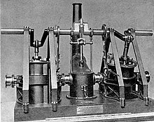 Modell einer Maschine von Maudslay
 -
 1853 von J. & A. Blyth in London gebaute Oszillierende Dampfmaschine des DDSG-Dampfers Orsova
 -
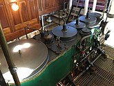
 Zweizylinder-Verbundmaschine der Gisela (1870) mit Steuerung über lose Exzenter und mittig gelegenem Kondensator


Schrägliegend[Bearbeiten | Quelltext bearbeiten]
Diese Bauart kam ab der zweiten Hälfte des 19. Jahrhunderts bei Raddampfern zum Einsatz und zeichnete sich durch eine größere Leistungsfähigkeit und Laufruhe gegenüber der oszillierenden Dampfmaschine aus, benötigte jedoch auch mehr Platz im Schiffskörper. Schrägliegende Dampfmaschinen erreichten bei Schaufelraddampfern eine sehr große Verbreitung und wurden vor allem als Verbunddampfmaschinen gebaut. Andere Bauformen waren Einzylindermaschinen (im Donauschiffer-Jargon auch als "Einspänner" bezeichnet) und Dreizylindermaschinen (sog. Triplexmaschine).
Vertikal[Bearbeiten | Quelltext bearbeiten]
As steamships grew steadily in size and tonnage through the course of the 19th century, the need for low profile, low centre-of-gravity engines correspondingly declined. Freed increasingly from these design constraints, engineers were able to revert to simpler, more efficient and more easily maintained designs. The result was the growing dominance of the so-called "vertical" engine[20] (more correctly known as the vertical inverted direct acting engine).
In this type of engine, the cylinders are located directly above the crankshaft, with the piston rod/connecting rod assemblies forming a more or less straight line between the two.[20] The configuration is similar to that of a modern internal combustion engine (one notable difference being that the steam engine is double acting, see below, whereas almost all internal combustion engines generate power only in the downward stroke). Vertical engines are sometimes referred to as "hammer", "forge hammer" or "steam hammer" engines, due to their roughly similar appearance to another common 19th-century steam technology, the steam hammer.[23]
Vertical engines came to supersede almost every other type of marine steam engine toward the close of the 19th century.[20][23] Because they became so common, vertical engines are not usually referred to as such, but are instead referred to based upon their cylinder technology, i.e. as compound, triple-expansion, quadruple-expansion etc. The term "vertical" for this type of engine is imprecise, since technically any type of steam engine is "vertical" if the cylinder is vertically oriented. An engine someone describes as "vertical" might not be of the vertical inverted direct-acting type, unless they use the term "vertical" without qualification.
-
 Diagram of a simple "hammer" engine
 -
 Vertical triple-expansion engine of Vorlage:USS. The typical vertical engine arrangement of cylinder, piston rod, connecting rod and crankshaft can clearly be seen in this photo.

_engines_cropped.JPG)
Trunk[Bearbeiten | Quelltext bearbeiten]
The trunk engine, another type of direct-acting engine, was originally developed as a means of reducing an engine's height while retaining a long stroke. (A long stroke was considered important at this time because it reduced the strain on components.)
A trunk engine locates the connecting rod within a large-diameter hollow piston. This "trunk" carries almost no load. The interior of the trunk is open to outside air, and is wide enough to accommodate the side-to-side motion of the connecting rod, which links a gudgeon pin at the piston head to an outside crankshaft.
The walls of the trunk were either bolted to the piston or cast as one piece with it, and moved back and forth with it. The working portion of the cylinder is annular or ring-shaped, with the trunk passing through the centre of the cylinder itself.[24][25]
Early examples of trunk engines had vertical cylinders. However, ship builders quickly realized that the type was compact enough to lay horizontally across the keel. In this configuration, it was very useful to navies, as it had a profile low enough to fit entirely below a ship's waterline, as safe as possible from enemy fire. The type was generally produced for military service by John Penn.
Trunk engines were common on mid-19th century warships.[25] They also powered commercial vessels, where—though valued for their compact size and low centre of gravity—they were expensive to operate. Trunk engines, however, did not work well with the higher boiler pressures that became prevalent in the latter half of the 19th century, and builders abandoned them for other solutions.[25]
Trunk engines were normally large, but a small, mass-produced, high-revolution, high-pressure version was produced for the Crimean War. In being quite effective, the type persisted in later gunboats.[26] An original trunk engine of the gunboat type exists in the Western Australian Museum in Fremantle. After sinking in 1872, it was raised in 1985 from the Vorlage:SS and can now be turned over by hand.[27] The engine's mode of operation, illustrating its compact nature, could be viewed on the Xantho project's website.[28]
-
 Trunk engine illustration
 -
 Cutaway view of trunk engine of Anmerkung: HMS – manchmal auch mit Satzzeichen geschrieben als H.M.S. – ist ein Akronym bzw. Abkürzung für „His Majesty's Ship“ oder „Her Majesty's Ship“ (englisch „Seiner bzw. Ihrer Majestät Schiff“) und ist seit 1789 das offizielle Namenspräfix, welches alle Kriegsschiffe im Dienst der britischen Marine führen., showing (on the left) engine cylinder, annular piston and trunk assembly, and connecting rod inside trunk
 -
 Looking down at the trunk engine of Anmerkung: HMS – manchmal auch mit Satzzeichen geschrieben als H.M.S. – ist ein Akronym bzw. Abkürzung für „His Majesty's Ship“ oder „Her Majesty's Ship“ (englisch „Seiner bzw. Ihrer Majestät Schiff“) und ist seit 1789 das offizielle Namenspräfix, welches alle Kriegsschiffe im Dienst der britischen Marine führen.. The connecting rod can be seen emerging from the trunk at right.


Rückwirkend[Bearbeiten | Quelltext bearbeiten]
The back-acting engine, also known as the return connecting rod engine, was another engine designed to have a very low profile. The back-acting engine was in effect a modified steeple engine, laid horizontally across the keel of a ship rather than standing vertically above it.[29] Instead of the triangular crosshead assembly found in a typical steeple engine however, the back-acting engine generally used a set of two or more elongated, parallel piston rods terminating in a crosshead to perform the same function. The term "back-acting" or "return connecting rod" derives from the fact that the connecting rod "returns" or comes back from the side of the engine opposite the engine cylinder to rotate a centrally located crankshaft.[30]
Back-acting engines were another type of engine popular in both warships and commercial vessels in the mid-19th century, but like many other engine types in this era of rapidly changing technology, they were eventually abandoned for other solutions. There is only one known surviving back-acting engine—that of the TV Emery Rice (formerly Vorlage:USS), now the centerpiece of a display at the American Merchant Marine Museum.[31][32]
-
 Diagram of back-acting engine of Vorlage:USS
 -
 Return connecting rod engine of HMS Agincourt (1865)


Definition über die Bauart der Zylinder[Bearbeiten | Quelltext bearbeiten]
Einfachexpansion (Zwillingsmaschine)[Bearbeiten | Quelltext bearbeiten]
Eine Einfachexpansions-Maschine ist eine Dampfmaschine, die den Dampf nur in einer Stufe dehnt, das heißt, alle ihre Zylinder werden mit dem gleichen Druck betrieben. Da dies in der Frühzeit der Schiffsmotorenentwicklung der mit Abstand häufigste Motorentyp war, trifft man selten auf den Begriff „einfache Expansion“. Es wird davon ausgegangen, dass ein Motor eine einfache Erweiterung ist, sofern nicht anders angegeben.
Verbundmaschine[Bearbeiten | Quelltext bearbeiten]
A compound engine is a steam engine that operates cylinders through more than one stage, at different pressure levels. Compound engines were a method of improving efficiency. Until the development of compound engines, steam engines used the steam only once before they recycled it back to the boiler. A compound engine recycles the steam into one or more larger, lower-pressure second cylinders first, to use more of its heat energy. Compound engines could be configured to either increase a ship's economy or its speed. Broadly speaking, a compound engine can refer to a steam engine with any number of different-pressure cylinders—however, the term usually refers to engines that expand steam through only two stages, i.e., those that operate cylinders at only two different pressures (or "double-expansion" engines).[33]
Note that a compound engine (including multiple-expansion engines, see below) can have more than one set of variable-pressure cylinders. For example, an engine might have two cylinders operating at pressure x and two operating at pressure y, or one cylinder operating at pressure x and three operating at pressure y. What makes it compound (or double-expansion) as opposed to multiple-expansion is that there are only two pressures, x and y.[34]
The first compound engine believed to have been installed in a ship was that fitted to Henry Eckford by the American engineer James P. Allaire in 1824. However, many sources attribute the "invention" of the marine compound engine to Glasgow's John Elder in the 1850s. Elder made improvements to the compound engine that made it safe and economical for ocean-crossing voyages for the first time.[35][36]
Dreifach- bzw. Mehrfachexpansion[Bearbeiten | Quelltext bearbeiten]
A triple-expansion engine is a compound engine that expands the steam in three stages, e.g. an engine with three cylinders at three different pressures. A quadruple-expansion engine expands the steam in four stages, and so on.[34] However, as explained above, the number of expansion stages defines the engine, not the number of cylinders, e.g. the RMS Titanic had four-cylinder, triple-expansion engines.[37] The first successful commercial use was an engine built at Govan in Scotland by Alexander C. Kirk for the SS Aberdeen in 1881.[38]
Multiple-expansion engine manufacture continued well into the 20th century. All 2,700 Liberty ships built by the United States during World War II were powered by triple-expansion engines, because the capacity of the US to manufacture marine steam turbines was entirely directed to the building of warships. The biggest manufacturer of triple-expansion engines during the war was the Joshua Hendy Iron Works. Toward the end of the war, turbine-powered Victory ships were manufactured in increasing numbers.[39]
-
 A Joshua Hendy triple-expansion engine
 -
 A triple-expansion engine on the Lydia Eva (steam drifter)
 -
 A triple-expansion engine on the 1907 oceangoing tug Hercules
 -
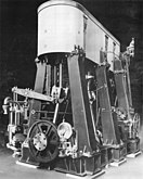 140-ton – also described as 135-ton – vertical triple-expansion engine of the type used to power World War II Liberty ships, assembled for testing prior to delivery. The engine is 21 feet (6.4 meters) long and 19 feet (5.8 meters) tall and was designed to operate at 76 rpm and propel a Liberty ship at about 11 knots (12.7 mph; 20.4 km/h).


Siehe auch[Bearbeiten | Quelltext bearbeiten]
Literatur[Bearbeiten | Quelltext bearbeiten]
- American Society of Mechanical Engineers (1978): Joshua Hendy Iron Works - informational brochure.
- Buell, Augustus C. (1906): The Memoirs of Charles H. Cramp, J. B. Lippincott Co., Philadelphia and London, pp. 92–93.
- Chatterton, E. Keble (1910): Steamships and their Story, page 132, Cassell and Company Ltd.
- Dumpleton, Bernard (2002): The Story Of The Paddle Steamer, Intellect Books (UK), Vorlage:ISBN.
- Evers, Henry (1873): Steam and the Steam Engine: Land, Marine and Locomotive, William Collins, Sons & Co., London and Glasgow.
- Fox, Stephen (2003): Transatlantic: Samuel Cunard, Isambard Brunel, and the Great Atlantic Steamships, HarperCollins, Vorlage:ISBN.
- Fry, Henry (1896): The History of North Atlantic Steam Navigation: With Some Account of Early Ships and Shipowners, Sampson Low, Marston & Co., London.
- Harvey, Steven (2007): It Started With a Steamboat: An American Saga, Authorhouse, p. 55, Vorlage:ISBN
- Hilton, George W. (2002): Lake Michigan Passenger Steamers, Stanford University Press, p. 59, Vorlage:ISBN.
- Kludas, Arnold (2000?): Record Breakers of the North Atlantic: Blue Riband Liners 1838–1952, Brassey's, Inc., Washington, D.C., Vorlage:ISBN.
- Laxton, Frederick William (1855): The Civil Engineer and Architect's Journal, incorporated with The Architect, Volume XVIII, John Knott, London.
- MacLehose, James (1906): Memoirs and portraits of one hundred Glasgow men who have died during the last thirty years and in their lives did much to make the city what it now is, James MacLehose & Sons, Glasgow, p. 118, as reproduced by the Glasgow Digital Library.
- Maginnis, Arthur J. (1900): The Atlantic Ferry: Its Ships, Men and Working, Whittaker and Co., London and New York.
- Murray, Robert (1858): Rudimentary Treatise on Marine Engines and Steam Vessels: Together with Practical Remarks on the Screw and Propelling Power as Used in the Royal and Merchant Navy, Published by J. Weale.
- Seaton, Albert Edward (1885): A Manual Of Marine Engineering - Comprising The Designing, Construction, And Working Of Marine Machinery, 4th Edition, Charles Griffin & Co., London.
- Sennett, Richard and Oram, Sir Henry J. (1918): The Marine Steam Engine: A Treatise for Engineering Students, Young Engineers, and Officers of the Royal Navy and Mercantile Marine, Longmans, Green & Co., London, New York, Bombay and Calcutta.
- Sutherland, John Lester (2004): Steamboats of Gloucester and the North Shore, The History Press, Vorlage:ISBN, pp. 31-32.
- Thurston, Robert Henry (1883): A History of the Growth of the Steam-engine, reprinted 2001 by Adamant Media Corporation, Vorlage:ISBN.
- Ward, J. H.: (1864): A Popular Treatise on Steam, and its Application to the Useful Arts, Especially to Navigation, D. Van Nostrand, New York, p. 60.
Weblinks[Bearbeiten | Quelltext bearbeiten]
- Video of model vibrating-lever engine of USS Monitor at YouTube
- Inclined inverted oscillating engine video at YouTube
- Tradition Sidewheel Steamboat Walking Beam Engine at YouTube
Einzelnachweise[Bearbeiten | Quelltext bearbeiten]
- ↑ Fry, p. 27.
- ↑ Fry, pp. 37-42.
- ↑ Fry, Chapter 5.
- ↑ Sennett and Oram, pp. 2-4.
- ↑ a b Murray, p. 4.
- ↑ a b Fox, p. 119.
- ↑ Sennett and Oram, p. 2-4.
- ↑ a b Sennet and Oram, p. 3.
- ↑ Maginnis, p. xiv.
- ↑ Commander P.M., RN Rippon: The evolution of engineering in the Royal Navy. Band 1. Spellmount, 1998, ISBN 0-946771-55-3, S. 19–20.
- ↑ a b Seaton, pp. 3-5.
- ↑ a b Thurston, p. 379.
- ↑ Sutherland, p. 31.
- ↑ Buell, pp. 92-93.
- ↑ Hebert.
- ↑ Evers, p. 88.
- ↑ Dumpleton, p. 83.
- ↑ Evers, p. 89.
- ↑ a b Murray, p. 14.
- ↑ a b c d Sennett and Oram, p. 12.
- ↑ a b Chatterton, p. 132.
- ↑ Scherer: Vom Raddampfer zum Schubverband.
- ↑ a b Evers, p. 81.
- ↑ Evers, pp. 90–91.
- ↑ a b c Sennett and Oram, pp. 7–8. See also the preceding section in this reference, entitled "Horizontal engines".
- ↑ G. A. Osbon: The Crimean gunboats. Part 1. In: The Mariner's Mirror. 51. Jahrgang, Nr. 2, 1965, ISSN 0025-3359, S. 103–116, doi:10.1080/00253359.1965.10657815.
- ↑ The Children - Western Australian Museum. In: Western Australian Museum. Abgerufen am 27. März 2018.
- ↑ Restoring the Xantho engine. 10. August 2011, archiviert vom am 10. August 2011; abgerufen am 27. März 2018.
- ↑ "Emory Rice T. V. Engine (1873)" web.archive.org Fehler bei Vorlage * Parametername unbekannt (Vorlage:Webarchiv): "date" Fehler bei Vorlage:Webarchiv: Genau einer der Parameter 'wayback', 'webciteID', 'archive-today', 'archive-is' oder 'archiv-url' muss angegeben werden. Fehler bei Vorlage:Webarchiv: enWP-Wert im Parameter 'url'., American Society of Mechanical Engineers, p. 4.
- ↑ Sennett and Oram, pp. 7,9.
- ↑ Emery Rice T. V. Engine (1873) web.archive.org Fehler bei Vorlage * Parametername unbekannt (Vorlage:Webarchiv): "date" Fehler bei Vorlage:Webarchiv: Genau einer der Parameter 'wayback', 'webciteID', 'archive-today', 'archive-is' oder 'archiv-url' muss angegeben werden. Fehler bei Vorlage:Webarchiv: enWP-Wert im Parameter 'url'., American Society of Mechanical Engineers brochure.
- ↑ Emery Rice web.archive.org Fehler bei Vorlage * Parametername unbekannt (Vorlage:Webarchiv): "date" Fehler bei Vorlage:Webarchiv: Genau einer der Parameter 'wayback', 'webciteID', 'archive-today', 'archive-is' oder 'archiv-url' muss angegeben werden. Fehler bei Vorlage:Webarchiv: enWP-Wert im Parameter 'url'., American Maritime Museum.
- ↑ Thurston, 391-396.
- ↑ a b Fry, Chapter XI.
- ↑ MacLehose, p. 118.
- ↑ Thurston, pp. 393-396.
- ↑ Samuel Halpern: Titanic's Prime Mover – An Examination of Propulsion and Power. In: Titanicology. 31. Januar 2011, abgerufen am 1. Februar 2021.
- ↑ Day, Lance and McNeil, Ian (Editors) 2013, Biographical Dictionary of the History of Technology Routledge, Vorlage:ISBN (P. 694)
- ↑ Joshua Hendy Iron Works web.archive.org Fehler bei Vorlage * Parametername unbekannt (Vorlage:Webarchiv): "date" Fehler bei Vorlage:Webarchiv: Genau einer der Parameter 'wayback', 'webciteID', 'archive-today', 'archive-is' oder 'archiv-url' muss angegeben werden. Fehler bei Vorlage:Webarchiv: enWP-Wert im Parameter 'url'. - American Society of Mechanical Engineers.